
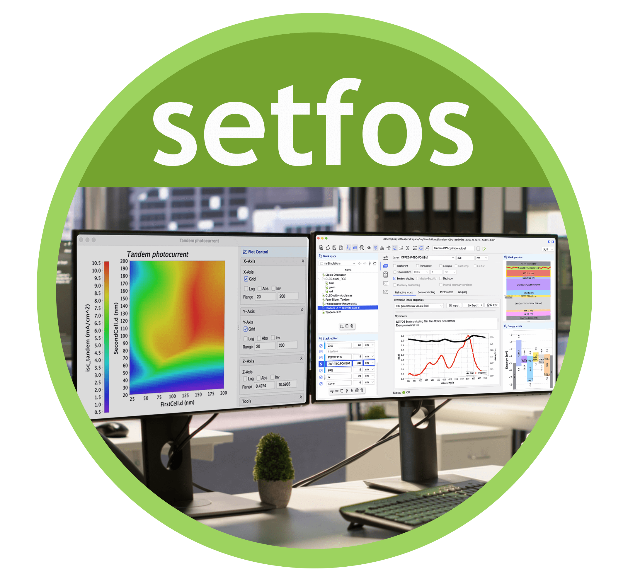
Setfos Emission Module
Light Emission Simulation
Setfos simulates light emission in OLEDs using a dipole emission model. You can calculate efficiency, angular color, brightness, and mode distribution—including waveguided and plasmonic modes. It's ideal for designing OLED stacks with color filters and optimizing outcoupling layers.
Several device properties can be modelled:
Electroluminescence emission pattern.
Micro-cavity effects by thin-film optics.
Photophysical properties such as efficiency, angular color, and brightness changes.
Excitonic processes in OLEDs by combining optical and electrical simulation.
Waveguided and plasmonic modes, quenching, distribution, and orientation of the emitters.
A number of scientific publications demonstrate the potential of Setfos for OLED modeling.
Efficiency and Emitted Color
Setfos calculates the optical parameters of an OLED by taking into account the full micro-cavity behavior.
This includes but it is not limited to:
CIE xy color coordinates.
Brightness (cd/m2).
Luminous Efficacy (Lm/W).
Luminous Current Efficiency (lm/A).
Correlated Color Temperature (CCT).
Color Rendering Index (CRI).
Reflectance, transmittance, and absorbance.
Mode Analysis
Setfos Mode Analysis can analyze light emission through the different emission channels of an OLED. The emitted light is either escaping to the far-field or waveguided inside the OLED layers. Without outcoupling structures, only the light emitted inside the escape cone is visible to the observer.
Mode analysis simulation calculates the contribution of the different optical modes to the total emitted power:
Air modes escaping to the outside.
Substrate modes waveguided in the carrier substrate.
Organic modes waveguided in the organic semiconductor stack.
Plasmon modes coupled to the metal electrodes.
Non-radiative quenching losses.
Modes can be inspected across the spectrum or summarized taking into account the spectral distribution of the emitter.
Simulation of waveguided modes across the visible spectrum
Coatings, Filters and Thin Film Optics
An OLED design is not limited to the stack of organic semiconductors. There are also color filters and anti-reflection layers that are used to obtain a higher lighting efficiency.
Setfos calculates the colour, angular variation, and polarization of the whole OLED stack, including coherent optics in the microcavity and coatings incoherently coupled through the substrate.
Simulation of A white oled stack with colour filter. norm_emission_WOLED with color filter
Emitter Profile, Optical Index, Dipole Orientation
Powerful fitting algorithms let you extract material parameters from measurement data. The optimization routines find the optimal combination of several variables.
Fitting of the emission zone in a complex multilayer stack. Find the spatial distribution of the emitting molecules.
Determine the optical n & k values from reflectance and transmittance measurement using the Sellmeier, Tauc-Lorentz, or Cauchy model.
Use spectral measurements to determine the intrinsic spectrum of an emitter/host system.
Determine the orientation of the emitter dipole by polarized spectroscopy or angular measurements.
Position-dependent Purcell Effect.
FAQs
-
You can simulate OLED light emission using Setfos by modeling the device as a multilayer stack and applying the dipole emission model. Setfos calculates angular- and wavelength-resolved electroluminescence spectra, including microcavity interference and polarization effects.
-
Setfos analyzes outcoupling efficiency using Mode Analysis, which integrates the dissipated dipole power over the in-plane wavevector. This process quantifies the power lost or extracted through various optical channels:
Out-coupled intensity (I_OC): Light radiated into the surrounding medium (e.g., air); this is the useful visible emission.
Substrate-guided intensity (I_SG): Power guided within the substrate layer, typically glass.
Guided-mode intensity (I_GM): Power confined within the active organic stack that cannot escape.
Evanescent-coupling intensity (I_EC): Energy coupled into surface plasmons or charge fluctuations at interfaces.
Absorption-loss intensity (I_AL): Power absorbed within the OLED structure.
Non-radiative intensity (I_NR): Power lost to non-radiative processes like quenching or thermalization.
This decomposition allows researchers to identify loss mechanisms and design efficient outcoupling strategies—such as scattering layers, microlens arrays, or nanostructures—to boost light extraction.
-
Setfos allows you to assign a dipole orientation distribution (isotropic, horizontal, vertical, or user-defined) and simulate its impact on emitted power, angular spectra, and outcoupling. This is critical for designing high-efficiency OLEDs using TADF or phosphorescent emitters.
-
Yes. Setfos simulates angular-dependent electroluminescence and spectral shifts caused by microcavity effects. You can extract CIE coordinates, CRI, and correlated color temperature (CCT) for various viewing angles.
-
Setfos includes emission profile fitting tools. You can fit the spatial distribution and width of the emission zone based on angle-resolved EL measurements. You can also extract n/k values or the intrinsic emitter spectrum from experimental data.
-
Setfos can model a complete OLED stack including multiple emission zones, color filters, and reflective layers. Thin-film optics and partially coherent light transfer are used to simulate real-world configurations such as WOLED + CF architectures.
-
Yes. You can input a custom emission spectrum and simulate its angular and spectral profile, taking into account refractive index, dipole orientation, and microcavity resonance.
-
Setfos calculates the Purcell factor as a function of dipole position and emission wavelength. This is crucial for understanding emission rate enhancement or suppression due to microcavity geometry.
-
Setfos is one of the few simulation platforms that accounts for all major loss channels:
Non-radiative recombination (via Drift-Diffusion module),
Non-radiative losses (via the internal quantum efficiency)
Waveguided and plasmonic losses (via Emission module),
Outcoupling through filters and coatings (via Advanced Optics module).
This makes it ideal for OLED stack optimization across all performance dimensions.

Shichen Yin, Organic Electronic Materials and Devices Laboratory (OEMDLab), NC State University
“I have used the Setfos to aid OLED optical design for over three years. Overall, the experience is good since it is easy to use and in good agreement with experimental results.”
Setfos Videos


T R I A L E V A L U A T I O N
TRY SETFOS FOR 1 MONTH
Experience the power of Setfos with a free one-month trial. Dive into advanced simulations for OLEDs and solar cells, and see firsthand how our software can optimize your research and development.