Stability of Perovskite Solar Cells: Literature Overview, Best Practices, and Required Tools
TL;DR:
Perovskite solar cell stability is improving but still faces challenges. ISOS protocols offer a practical and flexible framework to evaluate long-term performance under real-world conditions. Using tools like Fluxim’s Litos Lite, researchers can conduct standardized, parallel stability testing for deeper insights
Table of Contents
- Introduction: Why Stability Matters
- Understanding Perovskite Solar Cell Degradation
- Key Stressors Influencing Stability
- ISOS vs IEC Protocols
- T80 and Its Limitations
- ISOS Protocols Explained
- [Litos Lite Compatibility with ISOS Protocols](#Litos Lite Compatibility with ISOS Protocols)
- Choosing the Right Stability Testing Tools
- Research Examples Using Litos Lite
- Sample Layout and Measurement Accuracy
- Conclusion & Best Practices
- FAQs
- References
Introduction: Why Stability Matters
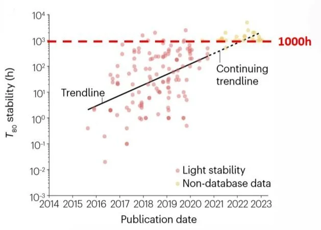
Perovskite solar cell stability has been a significant challenge in recent years. At the beginning of the development of this technology, the cells could barely last an hour under continuous testing, but progress has been steady. Today, researchers aim for a benchmark of 1,000 hours [1] during which the cells retain 80% of their initial performance — referred to as T80 stability. While this is a positive step forward, much more needs to be done to reach the long-term goal of 20-25 years of stability, which would make perovskite PVs competitive with silicon solar technologies.
Fig. 1 Perovskite Solar Cells aged at MPP under Continuous Illumination, H. Zhu et al., Nat Rev Mater 2023, 8, 569 [1].
Understanding Perovskite Solar Cell Degradation
Understanding the stability of a perovskite solar cell is a complex issue that goes beyond just tracking maximum power point (MPP) under constant illumination. Achieving long-term reliability requires deeper research and innovation across multiple aspects of this technology. To understand this, let's first break down what it really means.
Key Stressors Influencing Stability
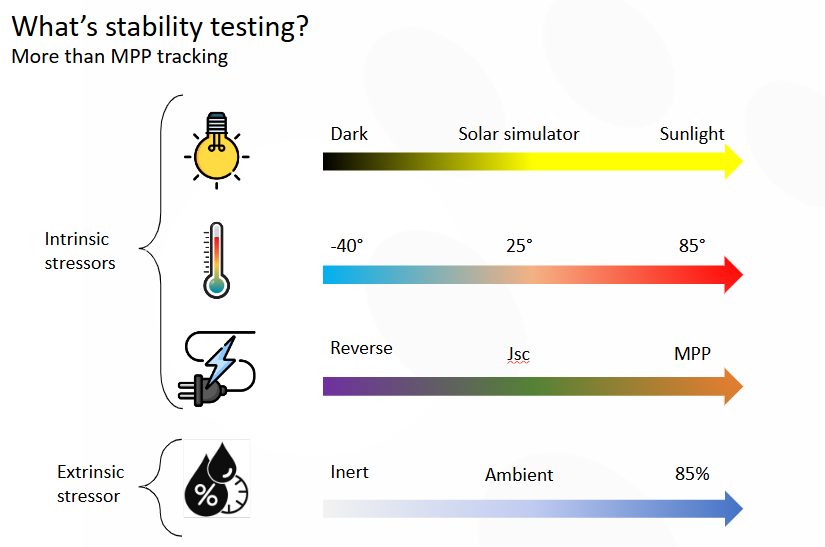
Fig. 2 Intrinsic and Extrinsic Stressors that influence perovskite solar cell stability.
Stability is influenced by various stressors, both intrinsic (from within the material) and extrinsic (from the environment) (Fig. 2). Extrinsic stressors include mainly oxygen and humidity. Each stressor can vary in intensity. For example, light can range from darkness to full sunlight, simulating outdoor conditions. The electrical bias can shift from reverse to maximum power point (MPP) and everything in between. Humidity can range from zero up to 85% or even more extreme testing conditions. These stressors are often combined to simulate realistic operational conditions.
Light: From dark to 1 sun
Temperature: -40°C to +85°C
Humidity: 0–85% RH
Electrical Bias: Reverse to MPP
The challenge lies in combining these stressors to create the right testing environment that simulates real-world conditions and helps us better understand and improve stability. For that we have protocols, which provide a framework for reliable stressing comparisons.
Fig 3. The two types of Protocol frameworks developed for testing solar cells in industry (IEC) and academia (ISOS)
ISOS vs IEC Protocols
The two main groups of protocols used for perovskite solar cells are the IEC and the ISOS. Both aim to provide reproducible and comparable results, combining stress conditions with device characterization. Characterization typically includes at least a JV (current-voltage) measurement to assess the device's power conversion efficiency (PCE). There is a key difference between the two protocols: the IEC protocols (see table below) have been developed for the testing of silicon solar cells, and they exploit testing tools that are available in industrial research labs. On the other hand, the ISOS protocols are guidelines grouped by academic researchers who work on the early-stage development of the technology. They were first proposed for the testing of organic solar cells and extended to the case of perovskite solar cells.
| Test ID | ST1 | ST2 | ST3 | ST4 |
|---|---|---|---|---|
| Description | Dry heat | UV exposure | Damp heat | Light exposure |
| Light | None | UV | None | Daylight (600–1000 W/m²) |
| Temperature | 45°C 65°C 85°C |
65°C | 45°C 65°C 85°C |
45°C 65°C 85°C |
| Humidity | Ambient | Ambient | 85% RH | Ambient |
| Environment | Oven | UV chamber | Climate chamber | Light soak chamber |
| Load | None | None | None | Passive or active, MPP |
The IEC test standards (ST1–ST4) were developed for silicon PVs and simulate harsh environmental conditions using industrial-scale equipment. While informative, they are often too rigid or resource-intensive for emerging technologies like perovskites.
While IEC and ISOS protocols are similar in their goal, they differ in approach significantly. IEC standards, although effective for many solar technologies, aren't well-suited for perovskite solar cells. These standards focus on replicating outdoor environmental stresses, structuring protocols around real-world conditions. However, this comes with a downside: the protocols require a complex set of facilities and equipment to recreate these conditions, making them more demanding in terms of resources. Additionally, IEC protocols haven’t been fully adapted to address the unique challenges of perovskite PV technologies, which limits their effectiveness for this particular material.
This means, for instance, that if we take the T80 (time until 80% efficiency remains) as a standardized figure of merit to assess the stability of perovskite, we see that this figure of merit is not compatible (Fig 5) or it's difficult to make it compatible with special decay behaviors typical of perovskite, like the burning effect, where the performance first increases and then decreases (left graph), or the irreversible decay, where the cell recovers after a period in dark (right graph).
T80 and Its Limitations
Fig 5. T80 as standardized figure of merit which is incompatible with reversible decay or burn-in effect
ISOS Protocols Explained
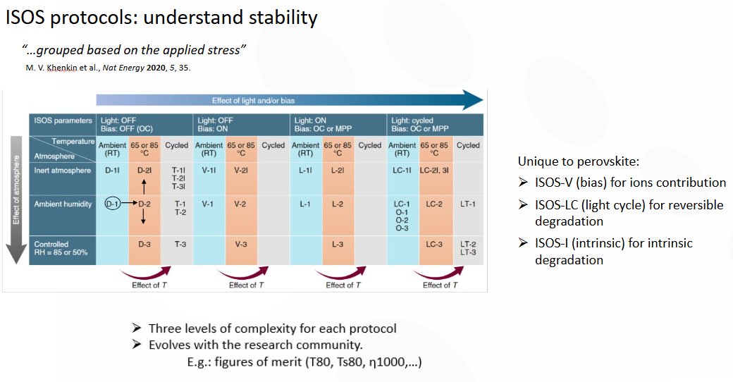
This is where ISOS protocols come in, providing a more flexible framework tailored for understanding the stability of perovskite solar cells. These protocols are organized based on the type of stress applied—whether it's light, electrical bias, or temperature. Each protocol increases in complexity with the increasing reference number, allowing for the gradual increment of the strength of the dressing conditions.
ISOS protocols are categorized by the type of stress applied:
D-series: Dark stability
L-series: Light stability
T-series: Thermal stress
M-series: MPP tracking
Each protocol increases in complexity with higher numbers (e.g. D1 < D2i).
Fig 6. ISOS protocols used to understand perovskite solar cell stability, grouped based on the applied stress [2]
Litos Lite Compatibility with ISOS Protocols
For example, the simplest protocol, D1 as shown in the table in Fig. 6, involves placing the solar cell in darkness at room temperature, which is easily achievable in any lab. As you move to more complex protocols, such as D2, a temperature stress is added with further possible adjustments, such as different atmospheres (humidity can be introduced e.g. in the D2i). This step-by-step increase allows researchers to simulate various stress levels and environmental conditions.
What makes ISOS useful for perovskites is that it includes protocols specifically designed to address unique challenges of these materials, such as ion migration or reversible degradation. These tailored approaches help researchers to better understand the intrinsic and extrinsic factors that affect perovskite stability.
Additionally, ISOS protocols evolve alongside advancements in the research community. While T80, which measures stability by assessing efficiency after 1,000 hours, is a key figure of merit, it's not the only one. Researchers have introduced a range of other metrics to capture various aspects of stability. These additional figures of merit provide a more comprehensive understanding of how solar cells, especially perovskite PVs, perform over time and under different conditions. This continuous evolution ensures that the protocols remain relevant and effective as our knowledge and technology progress.
Litos Lite supports multiple ISOS protocols including ISOS-D (dark storage), ISOS-V (bias stress), ISOS-T (thermal cycling), ISOS-L (light soaking), ISOS-O (outdoor), ISOS-LC (light cycling), and ISOS-LT (solar-thermal cycling). Note that certain advanced protocols requiring environmental chambers or specific humidity levels may not be compatible without additional equipment.
ISOS Protocol Overview
ISOS protocols are internationally recognized procedures for evaluating the long-term stability of solar cells under real-world conditions. Whether you're running dark storage (ISOS-D), light soaking (ISOS-L), or bias stress (ISOS-V) tests, choosing the right equipment is critical. The table below shows exactly which ISOS protocols can be executed using Fluxim’s Litos Lite — a high-throughput platform designed for parallel JV and stability testing of organic, perovskite, and tandem solar cells.
About the ISOS Protocols
ISOS (International Summit on Organic Photovoltaic Stability) protocols are divided into categories based on the type of stress applied:
- ISOS-D (Dark Storage): Stability in the absence of light at ambient or elevated temperature.
- ISOS-V (Bias Stress): Samples under electrical bias to test charge-induced degradation.
- ISOS-T (Thermal Cycling): Simulates outdoor temperature swings.
- ISOS-L (Light Soaking): Exposure to constant illumination.
- ISOS-O (Outdoor Stability): Real-world exposure conditions.
- ISOS-LC (Light Cycling): Repeated light-dark cycles to stress encapsulation and materials.
- ISOS-LT (Solar-Thermal): Combines light and temperature cycling — the most demanding tests.
Do you want a deeper explanation of each protocol and how they relate to solar cell stability? Read our full guide: ISOS Protocols for Perovskite Stability Testing.
If your lab requires high-throughput, ISOS-compliant testing, get in touch with us today to see how Litos Lite can support your solar cell research.
ISOS Protocols Compatibility with Litos Lite
This table summarizes the compatibility of Fluxim's Litos Lite system with standard ISOS stability testing protocols under various environmental and operational conditions.
| Protocol | Category | Light Condition | Temperature | Atmosphere | Load | Compatible with Litos Lite |
|---|---|---|---|---|---|---|
| Dark Storage (ISOS-D) | ||||||
| ISOS-D-1 | Dark Storage | Off | 25 / Ambient | Ambient | OC | Yes |
| ISOS-D-2 | Dark Storage | Off | 65, 85 | Ambient | OC | Yes |
| ISOS-D-3 | Dark Storage | Off | 65, 85 | 85% | OC | No |
| ISOS-D-1I | Dark Storage | Off | 25 / Ambient | Nitrogen | OC | Yes |
| ISOS-D-2I | Dark Storage | Off | 65, 85 | Nitrogen | OC | Yes |
| Bias Stability (ISOS-V) | ||||||
| ISOS-V-1 | Bias Stability | Off | 25 / Ambient | Ambient | OC, MPP, Vrev | Yes |
| ISOS-V-2 | Bias Stability | Off | 65, 85 | Ambient | OC, MPP, Vrev | Yes |
| ISOS-V-3 | Bias Stability | Off | 65, 85 | 85% | OC, MPP, Vrev | No |
| ISOS-V-1I | Bias Stability | Off | 25 / Ambient | Nitrogen | OC, MPP, Vrev | Yes |
| ISOS-V-2I | Bias Stability | Off | 65, 85 | Nitrogen | OC, MPP, Vrev | Yes |
| Thermal Cycling (ISOS-T) | ||||||
| ISOS-T-1 | Thermal Cycling | Off | Cycled:RT to 65, 85 | Ambient | OC | Yes |
| ISOS-T-2 | Thermal Cycling | Off | Cycled:RT to 65, 85 | Ambient | OC | Yes |
| ISOS-T-3 | Thermal Cycling | Off | Cycled:-40 to 85 | <55% | OC | No |
| ISOS-T-1I | Thermal Cycling | Off | Cycled:RT to 65, 85 | Nitrogen | OC | Yes |
| ISOS-T-2I | Thermal Cycling | Off | Cycled:RT to 65, 85 | Nitrogen | OC | Yes |
| ISOS-T-3I | Thermal Cycling | Off | Cycled:-40 to 85 | Nitrogen | OC | No |
| Light Soaking (ISOS-L) | ||||||
| ISOS-L-1 | Light Soaking | Constant | 25 / Ambient | Ambient | MPP or OC | Yes |
| ISOS-L-2 | Light Soaking | Constant | 65, 85 | Ambient | MPP or OC | Yes |
| ISOS-L-3 | Light Soaking | Constant | 65, 85 | 50% | MPP | No |
| ISOS-L-1I | Light Soaking | Constant | 25 / Ambient | Nitrogen | MPP or OC | Yes |
| ISOS-L-2I | Light Soaking | Constant | 65, 85 | Nitrogen | MPP or OC | Yes |
| Outdoor Stability (ISOS-O) | ||||||
| ISOS-O-1 | Outdoor Stability | Outdoor | Ambient Outdoor | Ambient | MPP or OC | No |
| ISOS-O-2 | Outdoor Stability | Outdoor | Ambient Outdoor | Ambient | MPP or OC | (Yes) |
| ISOS-O-3 | Outdoor Stability | Outdoor | Ambient Outdoor | Ambient | MPP | No |
| Light Cycling (ISOS-LC) | ||||||
| ISOS-LC-1 | Light Cycling | Cycled | 25 / Ambient | Ambient | MPP or OC | Yes |
| ISOS-LC-2 | Light Cycling | Cycled | 65, 85 | Ambient | MPP or OC | Yes |
| ISOS-LC-3 | Light Cycling | Cycled | 65, 85 | <50% | MPP | No |
| ISOS-LC-1I | Light Cycling | Cycled | 25 / Ambient | Nitrogen | MPP or OC | Yes |
| ISOS-LC-2I | Light Cycling | Cycled | 65, 85 | Nitrogen | MPP or OC | Yes |
| Solar-Thermal Cycling (ISOS-LT) | ||||||
| ISOS-LT-1 | Solar-Thermal | Cycled | Cycled:RT to 65 | Ambient | MPP or OC | Yes |
| ISOS-LT-2 | Solar-Thermal | Cycled | Cycled:5 to 65 | 50% | MPP or OC | No |
| ISOS-LT-3 | Solar-Thermal | Cycled | Cycled:-25 to 65 | 50% | MPP or OC | No |
| ISOS-LT-1I | Solar-Thermal | Cycled | Cycled:RT to 65 | Nitrogen | MPP or OC | Yes |
| ISOS-LT-2I | Solar-Thermal | Cycled | Cycled:5 to 65 | Nitrogen | MPP or OC | No |
| ISOS-LT-3I | Solar-Thermal | Cycled | Cycled:-25 to 65 | Nitrogen | MPP or OC | No |
Litos Lite supports multiple ISOS protocols including ISOS-D (dark storage), ISOS-V (bias stress), ISOS-T (thermal cycling), ISOS-L (light soaking), ISOS-O (outdoor), ISOS-LC (light cycling), and ISOS-LT (solar-thermal cycling). Note that certain advanced protocols requiring environmental chambers or specific humidity levels may not be compatible without additional equipment.
Choosing the Right Stability Testing Tools
Perovskite Solar Cell Stability Analysis
| Stability Requirements |
 SMU |
MPP Tracker |
 Litos Lite |
|---|---|---|---|
| Parallel Stress (MPP or constant V) | ✗ | ✓ | ✓ |
| Parallel JV | ✗ | ✗ | ✓ |
| Current-Voltage (JV) in 4 Quadrants | ✓ | ✗ | ✓ |
| Software-Controlled Sun Simulator | ✗ | — | ✓ |
| Cycling (Light, JV, MPP…) | ✗ | ✗ | ✓ |
| Environment Control (T, Humidity…) | ✗ | — | ✓ |
Now that we have the ISOS framework, the next crucial step is having the right tool to perform these measurements. It's not just about replicating the protocols—you also need reliable comparisons and statistically valid results. To achieve this, the tool must support parallel stressing, meaning all pixels are stressed simultaneously, enabling parallel JV measurements to be taken. This ensures that both the stress conditions and characterization, as required by the protocols, happen in unison.
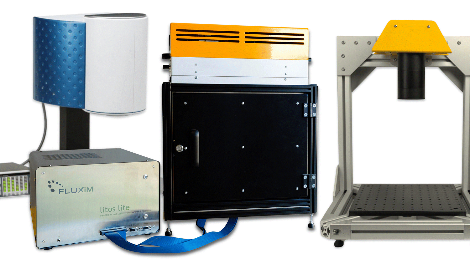
Fig 8. A selection of LED based solar simulators compatible with Litos Lite
Stressing the device with high temperatures and critical atmospheres isn't enough—you also need flexibility in applying different biases, both positive and negative, as well as controlling the current. A software-controlled sun simulator is essential for automating and synchronizing the measurement process, biasing, and illumination, which streamlines the entire experiment and improves accuracy. To conduct accurate and thorough stability measurements, you need to cycle through different types of measurements and control the environment, such as humidity or atmospheric conditions.
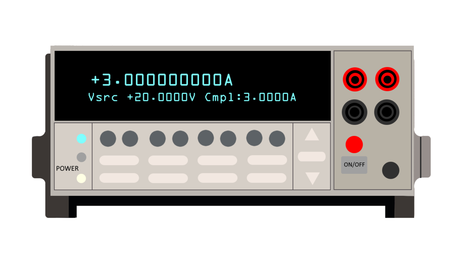
Fig 9. An example of an SMU used to perform JV measurements
Typical lab equipment, like a standard Source-Measuring-Unit (SMU), provides high-quality JV characterizations but is limited to testing one sample at a time. A SMU can be connected to a multiplexer for sequential testing, but even this doesn’t meet the requirement of measuring all samples in parallel under the exact conditions. Perovskite solar cells could degrade quickly under the solar simulator and a sequential JV characterization doesn’t allow you to perform a proper statistical analysis on devices under the same experimental conditions and history.
Fig 10. An example of an MPP tracker
Another common option is an MPP tracker (Fig.10), which is great for parallel stressing but primarily focuses on tracking the Maximum Power Point (MPP) of the solar cell. This electronics is a simple object that perfectly follows the MPP of multiple solar cells in parallel. However, it doesn’t offer parallel JV characterizations, and depending on the setup, you may or may not have control over the sun simulator or environmental conditions.
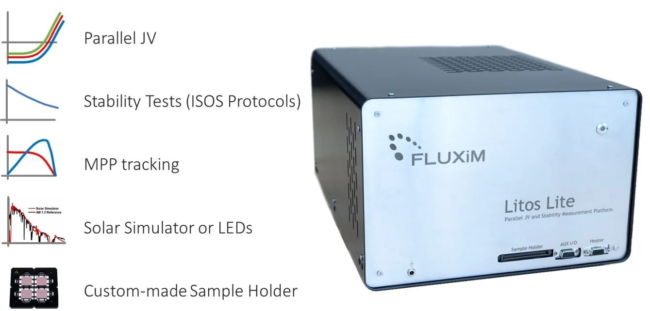
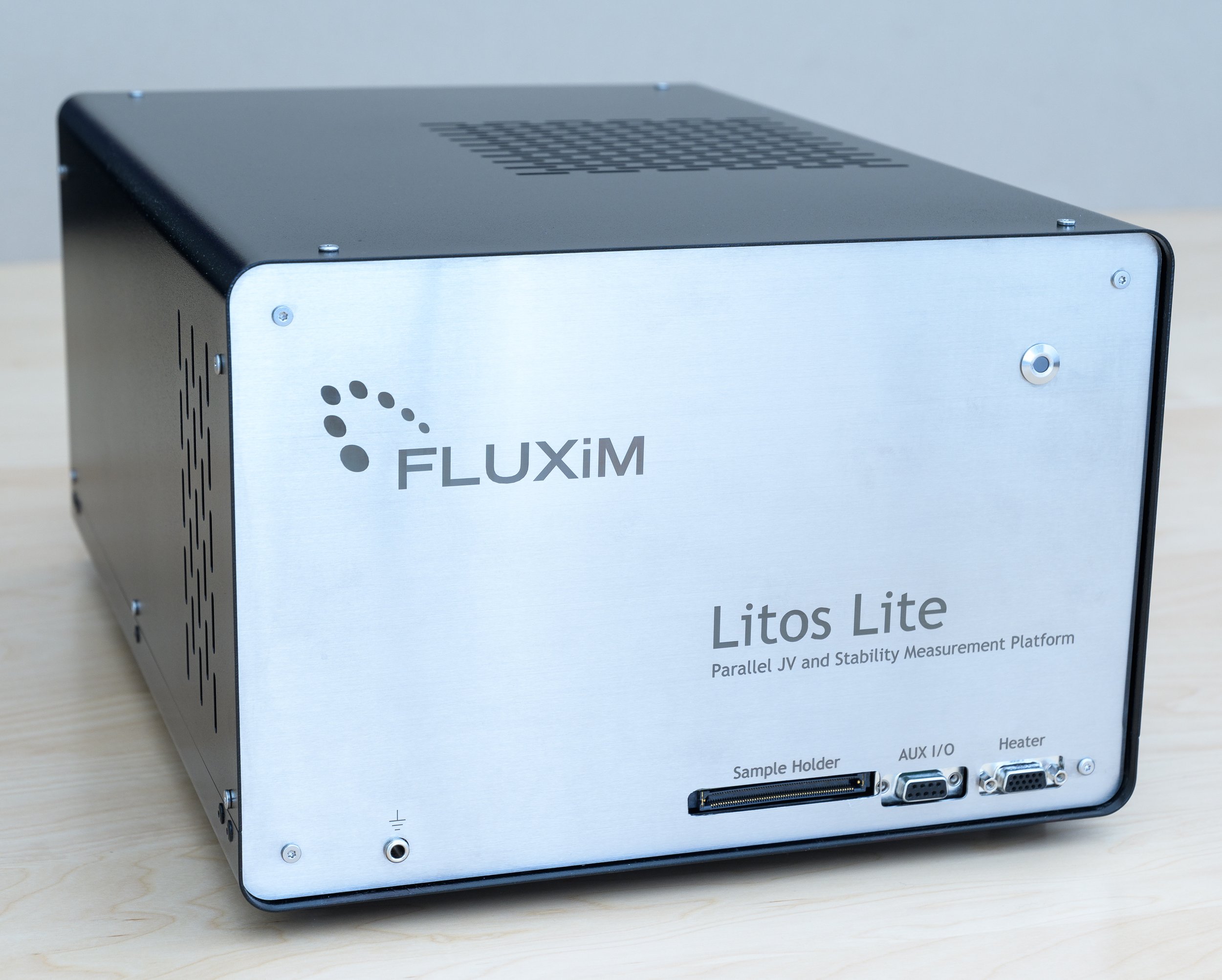
This is where Litos Lite from Fluxim comes in. It was designed to address all these challenges, providing parallel JV measurements, environmental control, and automation, allowing researchers to push stability research further with a comprehensive and tailored solution.
Research Examples Using Litos Lite
Fig. 11. Litos Lite, the Parallel JV and Stability Measurement Platform for Solar Cells from Fluxim AG
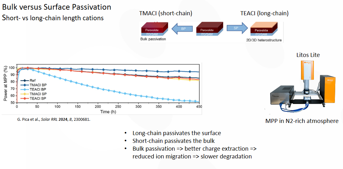
Let’s look at some examples of how this instrument can be used, and how it has been used by several research teams developing perovskite solar cells. Fig. 12 a study on passivation by Pica et al [3].
Fig. 12 A study on bulk vs. Surface passivation by Pica et al. Litos Lite is used to track the MPP of several solar cells in parallel.
Their idea was to compare the impact of bulk and surface passivation on stability by comparing the chain length of cations. What they observed is that long-chain cations tend to passivate the surface of the perovskite, while short-chain cations passivate the bulk material, both contributing to slower degradation. To ensure accurate analysis, their devices were placed in a nitrogen-rich atmosphere, eliminating any environmental interference. They then used Litos Lite for MPP tracking, highlighting the tool's precision in such experiments. This also underscores the importance of pilot testing. By comparing stability measurements between devices with different passivation techniques, researchers gain valuable insights into which methods offer better long-term performance.
It's not just the perovskite absorber itself that needs attention; the crystal phase stability of the material is also crucial. Specifically, the thermal stability of the crystal phase plays a key role in long-term performance.
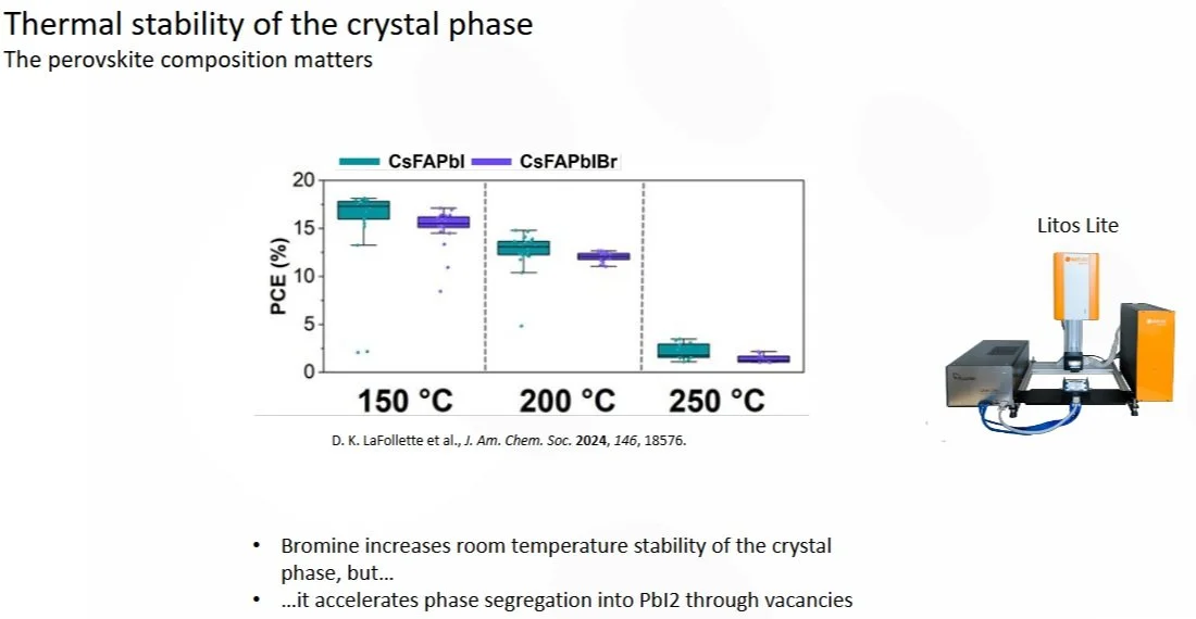
Fig 13. The thermal Stability of the Crystal phase influences the PCE of the solar cells [4].
A study by Lafollette et al. from Georgia Tech [4], explored this aspect. Instead of directly studying stability, they focused on collecting JV characterizations in parallel to assess how changes in the crystal phase affected the power conversion efficiency (PCE).
This approach highlights that beyond simply stabilizing the material, understanding how its crystal structure reacts under different conditions can provide insights into optimizing both performance and durability. Understanding stability involves looking at various factors, such as the use of bromine in the absorber material. In this study, the researchers compared absorbers with and without bromine. Bromine helps increase the crystal phase stability at room temperature, but it also accelerates phase degradation. The underlying mechanism is complex, as bromine enhances the formation of vacancies, which can eventually lower overall stability.
To investigate this, they performed parallel JV testing, ensuring that all devices were kept at a specific temperature and in the same environment to obtain statistically reliable data on device performance. The tests were conducted using Litos Lite, which enabled them to measure multiple solar cells simultaneously, providing a clearer picture of how bromine affects both performance and stability.
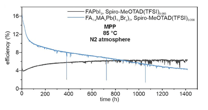
In addition to crystal phase thermostability, the stability of the entire device must be considered, as shown by a study from M. J. Grotevent et al. at MIT [5]. They found that a commonly used hole-transporting layer, spiro-MeOTAD, has relatively low thermal stability, remaining stable only up to 85°C. This temperature is too low for typical solar cell applications, which require higher tolerance.
Fig 14. Spiro-MeOTAD with additives grants high efficiency. Stability limited to 85°C .Additive-free Spiro has stability up to 115°C. Stable performance at 85°C in N2-rich atmosphere [5]
To address this, the team developed an additive-free spiro-MeOTAD layer that can withstand temperatures up to 115°C. In their experiments, they minimized environmental influence to focus on the transport layer’s stability and used parallel measurements to test multiple samples. A larger sun simulator, connected to Litos Lite, enabled accurate performance testing at 85°C. The device remained stable for nearly 1,500 hours, highlighting the need for improved transport layers to enhance long-term performance.
Fig 14. Spiro-MeOTAD with additives grants high efficiency. Stability limited to 85°C .Additive-free Spiro has stability up to 115°C. Stable performance at 85°C in N2-rich atmosphere [5]
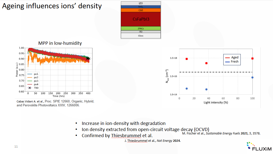
At Fluxim AG, we're not just selling tools for research. We actively engage in scientific research as well. One of our key findings is that aging not only affects perovskite solar cells but also impacts the behavior of mobile ions within them. While it is well known that perovskites contain highly mobile ions that contribute to device aging, our research suggests that aging, in turn, influences the movement of these ions.
To explore this, we conducted MPP tracking on a specific perovskite absorber, allowing us to closely observe how aging alters ion dynamics and, ultimately, the performance of the device. The device we studied is a cesium-based FAPbI, designed for bifacial applications. We conducted the experiment in low humidity conditions and reached 400 hours with a T90, meaning the device retained 90% of its initial performance [6]. To delve deeper, we combined this with advanced characterization techniques to investigate whether the mobile ions' behavior, such as their density or mobility, was affected by aging.
We performed open circuit voltage decay measurements, where the sample is illuminated, the light is then turned off, and the device is kept at open circuit voltage to observe how it decays. Using the analysis detailed in Fischer et al. [8], we extracted the ion density in the perovskite layer. The key finding was that aged devices consistently showed an ion density up to two orders of magnitude higher than fresh devices, regardless of light intensity. This observation was quite intriguing and was also confirmed by Thiesbrummel et al [7]. from Oxford PV.
While the exact cause of this increase in ion density is still unclear, it has been consistently observed across multiple types of perovskites, making it an important area for further research.
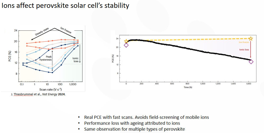
Fig 16. Ions affect perovskite solar cell’s stability. The stability depends on how the characterization is performed.
Thiesbrummel et al. also quantified the significant impact of mobile ions on both power conversion efficiency (PCE) and overall device stability. To do this, the team performed JV characterizations over a wide range of scan rates, exceeding 1,000 volts per second. At such high scan rates, the mobile ions are essentially "frozen," meaning they do not move, allowing her to measure the effective PCE of the device without interference from mobile ions, which can otherwise influence performance through a field screening effect.
The team applied this technique to both fresh and degraded perovskite devices. After about 1,600 hours of ageing, they observed that the PCE measured during MPP tracking had significantly decreased compared to the starting value. However, when performing JV characterizations under ion-freeze conditions (fast scan rates), the PCE was effectively restored, showing that the apparent performance loss was largely due to the influence of mobile ions rather than irreversible degradation of the device.
This highlights the crucial role that mobile ions play in both the measurement of PCE and the stability of perovskite solar cells, emphasizing the need to account for these effects when evaluating device performance over time.
Fig 17. Reverse bias stability is required for the commercialization of perovskite solar cells. A cell goes in reverse bias when there is partial shading of the cell/module.
So far, we've mainly discussed operational stability, focusing on positive voltages. However, reverse bias is equally important for the commercialization of solar cells. Reverse bias testing is crucial because it simulates real-world conditions, such as partial shading from leaves, birds, or debris that may fall on the solar panel [9]. Understanding how different perovskite formulations respond to reverse bias is essential in advancing their commercial viability for long-term outdoor use.
For this type of testing, you need a tool capable of measuring potential and current across all four quadrants of the IV spectrum. Reverse bias is particularly challenging for perovskite solar cells, as they are known to be unstable and prone to shunting or damage even under short reverse bias conditions.
Fig 18. Perovskite/Silicon tandem solar cells stable under reverse bias conditions. The silicon sub-cell absorbs the reverse bias.
A standard single-junction perovskite solar cell is extremely vulnerable to reverse bias. It is well known that after exposure of a PSC to a reverse bias of just -2.5V — not uncommon in outdoor conditions — the device show unstable JV characteristics, making the measurements less reliable. This is why it is important to emphasize again the importance of parallel JV testing. It allows for accurate and real-time comparisons of device stability under stress.
Recently, an interesting finding revealed that perovskite PVs with carbon-based electrodes can endure reverse bias, withstanding negative voltages up to – 6V for 20 minutes without significant damage. This makes them potentially more suitable for real-world outdoor applications where shading and reverse bias would surely occur. Moreover, there's an interesting solution when you combine a perovskite solar cell with a silicon PV in a monolithic tandem solar cell. In this case, the silicon layer absorbs most of the reverse bias, resulting in overall stability that is more similar to silicon than the perovskite PV alone. This hybrid approach is a promising direction for the commercialization of perovskite photovoltaics, as it improves stability without sacrificing performance.
Before we wrap this up, we want to leave you with a key insight from Fluxim’s work in the lab and collaborations with customers: the layout of the sample itself plays a crucial role in testing. Getting this right is vital to ensuring accurate, reproducible results when evaluating perovskite stability and performance.
Sample Layout and Measurement Accuracy
Fig. 19 The importance of the sample layout for the proper parallel test of a Perovskite/Silicon Solar Cell.
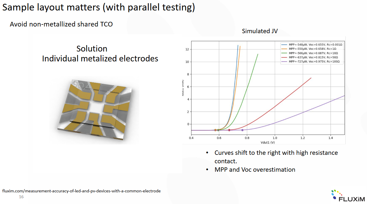
In parallel testing, the layout of the sample is crucial, especially when using a pre-structured TCO (transparent conductive oxide) substrate. These pre-structured TCO substrates are often chosen for larger-scale devices, where the TCO serves as the electrode for multiple pixels. Here's where the issue arises: if the TCO is not metallized, the higher resistance leads to voltage deviations, meaning you don’t accurately measure the true open-circuit voltage (VOC) or maximum power point (MPP) of your pixel. In the case of a common electrode, the situation becomes even more complex. The voltage measured depends not only on the pixel you are testing but also on the electrical condition of the neighboring pixel, as well as the total number of pixels connected to the same common electrode. For example, if one pixel is shunted, it will affect the measurement of the other pixels sharing that electrode.
Let’s consider a specific case where two pixels are being measured, and one is shunted. If you simulate the JV curve for the non-shunted pixel under varying resistance levels of the common electrode, you will see a clear pattern. As the contact resistance of the common electrode increases—from nearly zero up to 100 ohms—the JV curve shifts to the right. This results in an overestimation of both the MPP and VOC, especially at resistance values closer to reality, such as 1 or 10 ohms.
This example highlights the importance of carefully managing the electrical layout of your test samples to avoid unrealistic measurements, especially when working with non-metallized or common electrodes in upscaled devices. It is crucial to avoid common structured electrodes and minimize contact resistance to ensure accurate results.
Fig. 20 Sample layout matters with parallel testing. Individual anodes and cathodes are helpful if you want to make sure that the parallel measurements are reliable.
This is why Litos Lite is the ideal solution. It allows you to have multiple pixels on the same substrate while ensuring that each pixel has individual, metallized contacts. This setup minimizes contact resistance and avoids the issues caused by common structured electrodes, ensuring more accurate and reliable measurements.
Conclusion & Best Practices
Use ISOS for flexible, reproducible testing
Avoid relying solely on T80
Ensure proper sample layout
Use tools like Litos Lite to meet protocol requirements
The stability of perovskite solar cells is steadily improving, as evidenced by the growing data available in the Perovskite Database. To push further the boundaries of this development, MPP tracking alone is not sufficient. We need to focus on performing accurately the largest number of possible ISOS tests. The ISOS protocols offer a structured framework for addressing and understanding stability issues. To perform ISOS tests effectively, it's essential to use the right equipment that allows for pilot testing, ensuring reliable comparisons and controlled illumination and environmental conditions. Litos Lite is a perfect experimental platform for this purpose.
Lastly, when working with lab-scale devices, it's crucial to ensure that your sample layout is properly prepared for pilot testing and doesn't interfere with the accuracy of your measurements. This attention to detail is key to achieving valid and reliable results.
FAQs
What are ISOS protocols?
They are modular test procedures developed by the research community to evaluate solar cell stability under various stress conditions.
Why is T80 not always reliable?
Because perovskites may exhibit reversible degradation or burn-in effects, which distort the T80 result.
Why use Litos Lite for Perovskite Solar Cell Stability Analysis?
It supports parallel JV and MPP measurements with full control over bias and environment—ideal for ISOS testing.
References
[1] H. Zhu et al., Nat Rev Mater 2023, 8, 569.
[2] M. V. Khenkin et al., Nat Energy 2020, 5, 35.
[3] G. Pica et al., Solar RRL 2024, 8, 2300681.
[4] D. K. LaFollette et al., J. Am. Chem. Soc. 2024, 146, 18576.
[5] M. J. Grotevent et al., Advanced Energy Materials 2024, 2400456.
[7] J. Thiesbrummel et al., Nat Energy 2024.
[8] M. Fischer et al., Sustainable Energy Fuels 2021, 5, 3578.
For background on the development and importance of ISOS in perovskite research, see our blog article here.

